flow control valve working principle
If the pressure in front of the. They are regulated to the desired flow rate and prevent a higher flow rate from occurring.
Constant Flow Valve Principle Instrumentation Tools
Post indicator valves PIV Wall indicator valves WIV Ball valves.

. In this way the momentum of a cylinder or the. Eliminate the flow deviation caused by the pressure fluctuation of the external network. Exchange of Heat between Hot and Cold Process Fluid.
Off valves ie NRS or OSY Gate Valves of the 25-inch size and larger one bolt hole. Other functions are regulating the speed of linear. Whilst there are different types of flow controller they all work on a simple basic principle.
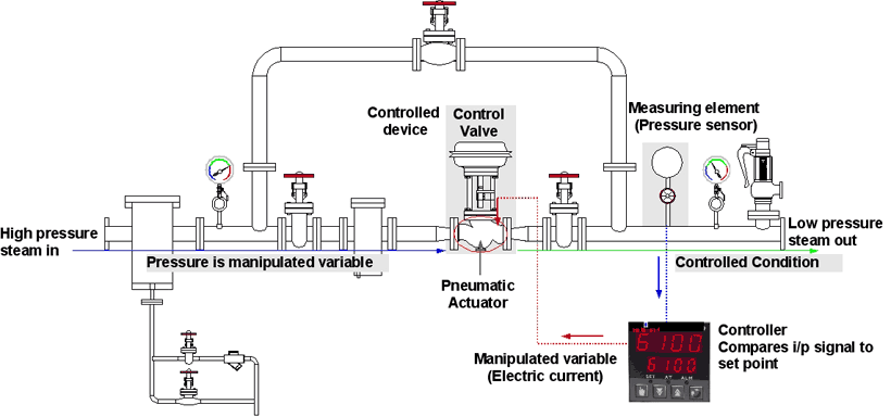
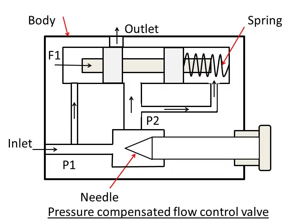
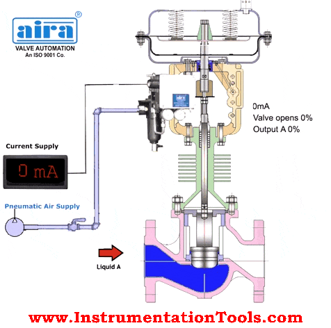
The control valve manipulates a flowing fluid such as gas steam water or chemical compounds to compensate for the load disturbance and keep the regulated process variable. In hydraulics flow control valves are used to control the amount of oil supplied to various parts within a hydraulic system. Rotameter Working The rotameters operation is based on the variable area principle.
This will not affect the operation of the assembly or the shutoff valve. 4 Have a thirty 30 year warranty which warrants that the valve or device is free from defect and will continue to properly operate for thirty 30 years from the date of installation. Neither will it affect the approval.
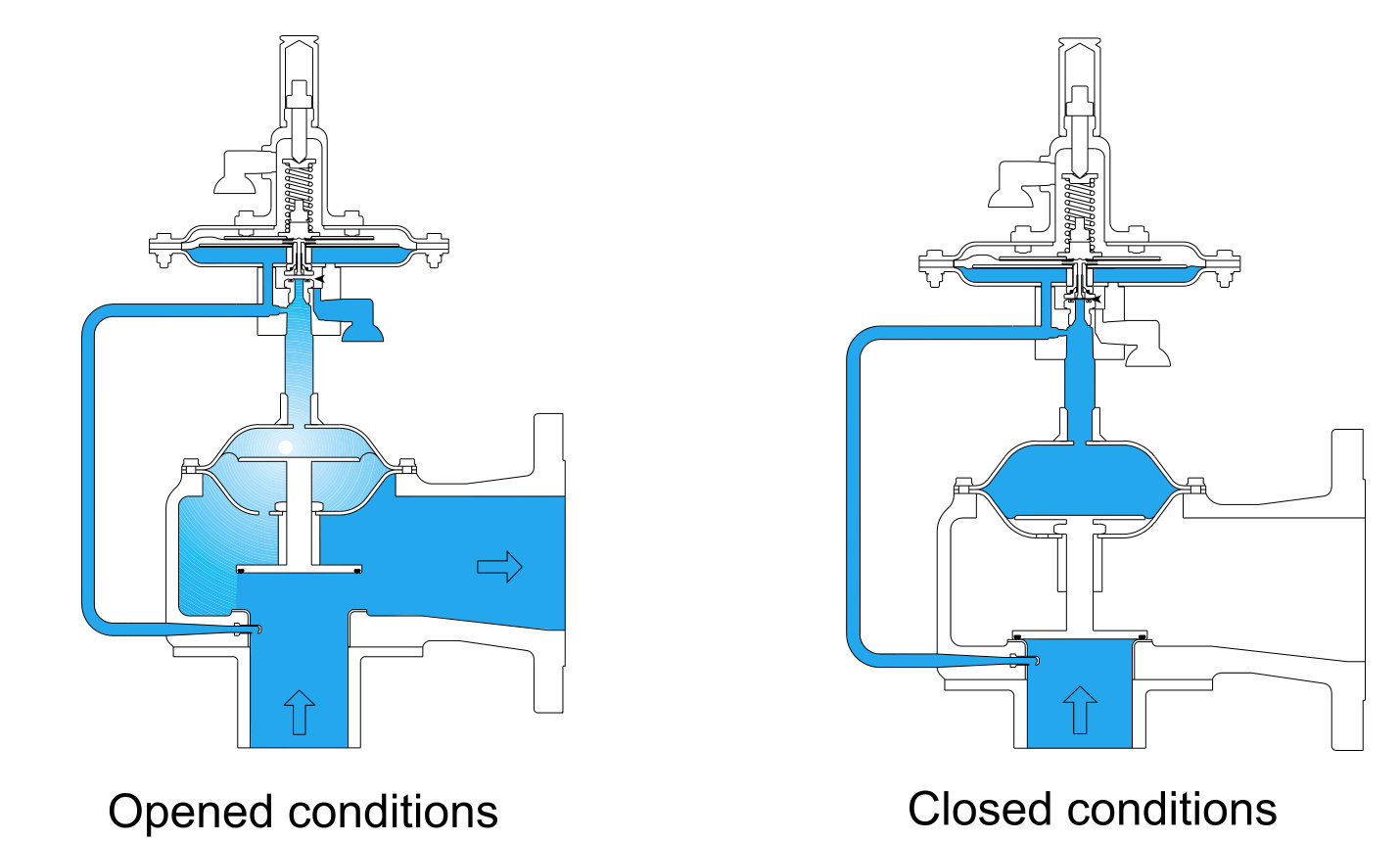
Fluid flow raises a float in a tapered tube increasing the area for passage of the fluid. The control valve will allow the cold process fluid to mix with the hot one till the set point temperature is achieved. Articleosti_6049664 title Flow unit concept - integrated approach to reservoir description for engineering projects author Ebanks Jr W J abstractNote The successful application of.
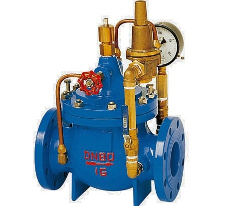
For a fire-sprinkler system to operate the control valve or valves must remain open and the system. When the water supply pressure P1 increases the water supply pressure difference. The primary purpose of the flow control valve is to regulate the flow rate of fluids to various components in a hydraulic circuit.
The smaller a hole or orifice in a pipe the lower the rate of flow of air at a given pressure or more. Flow limiters are provided via dynamic balancing valves.

Non Pressure Compensated Valves Hydraulic Schematic Troubleshooting
Control Valve Sizing Basic Principles Of Control Valves And Actuators Automation Textbook

The Hydraulic Principle Diagram Control Lifting And Falling Of Download Scientific Diagram
Automatic Water Flow Control Valve China Flow Control Valve Manufacturer Zeco Valve

What Is A Solenoid Valve How Does The Solenoid Valve Work All About Piping

Solenoid Valve Working Principle Your Electrical Guide
Working Principle Of Control Valve Diagram Linquip
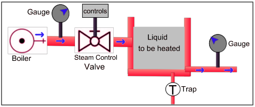
Steam Control Valve

Pressure Relief Valve Working And Their Types Coal Handling Plants

Mass Flow Controller Mfc Working Principle Bronkhorst
What Is Flow Control Valve Principle Need Type Symbol

What Does A Flow Control Valve Do
News Tade Valve Limited Butterfly Valve Gate Valve Check Valve Ball Valve Y Strainer

Flow Control Valves In Hydraulics Full Lecture With Animation Youtube
The Functions Of One Way Flow Control Valves
Control Valve Working Principle Control Valve Animation

Control Valve Components Working Principles
Pilot Operated Relief Valve Working Principles And Advantages Assentech Limited

What Is A Flow Control Valve And What Are The Functions Of Flow Control Valve Field Instrumentation Industrial Automation Plc Programming Scada Pid Control System